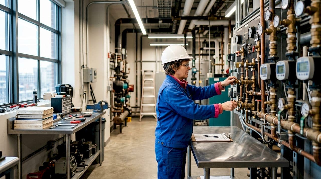
Hydronic heating in large commercial and institutional facilities operates as a closed-loop network where a central heat source warms water and pumps circulate it through a piping system to terminal units across the building. Those terminal units, whether fan coil units, radiant panels, or finned-tube radiators, extract heat from the water and release it into the occupied space. The cooled water then returns to the heat source to be reheated and sent out again. This continuous cycle is what makes hydronic systems so well suited to large facilities: the energy stays in the water, not in the air, and the distribution losses are far lower than with ducted forced-air systems.
The primary components of any large hydronic system are:
- Heat source: gas-fired condensing boilers, electric boilers, or heat pumps (air-to-water or ground-source)
- Circulation pumps: primary pumps serving the boiler loop, secondary pumps serving distribution circuits
- Piping network: supply and return mains, branch circuits, and risers connecting all zones
- Terminal units: fan coil units, radiant floor or ceiling panels, radiators, or convectors
- Controls: building automation systems (BAS), thermostats, zone valves, and variable speed drives
Zoned control is one of the defining features of commercial hydronic systems. A hospital ward, a school gymnasium, and an office corridor can each maintain different temperatures simultaneously, all served from the same central plant.
What piping arrangements and system types suit large buildings?
Large facilities rarely use a single simple loop. The scale and diversity of heating loads demand more sophisticated configurations, and the choice of system type has lasting consequences for energy use, balancing difficulty, and maintenance cost.
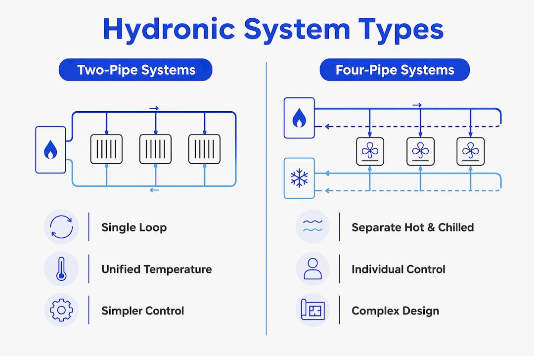
Two-pipe systems use a single set of supply and return mains. Every terminal unit draws from the same supply temperature, which works well for heating-only buildings but creates problems when some zones need cooling while others need heat. Changeover valves can switch the system between heating and cooling modes seasonally, though the transition is disruptive.
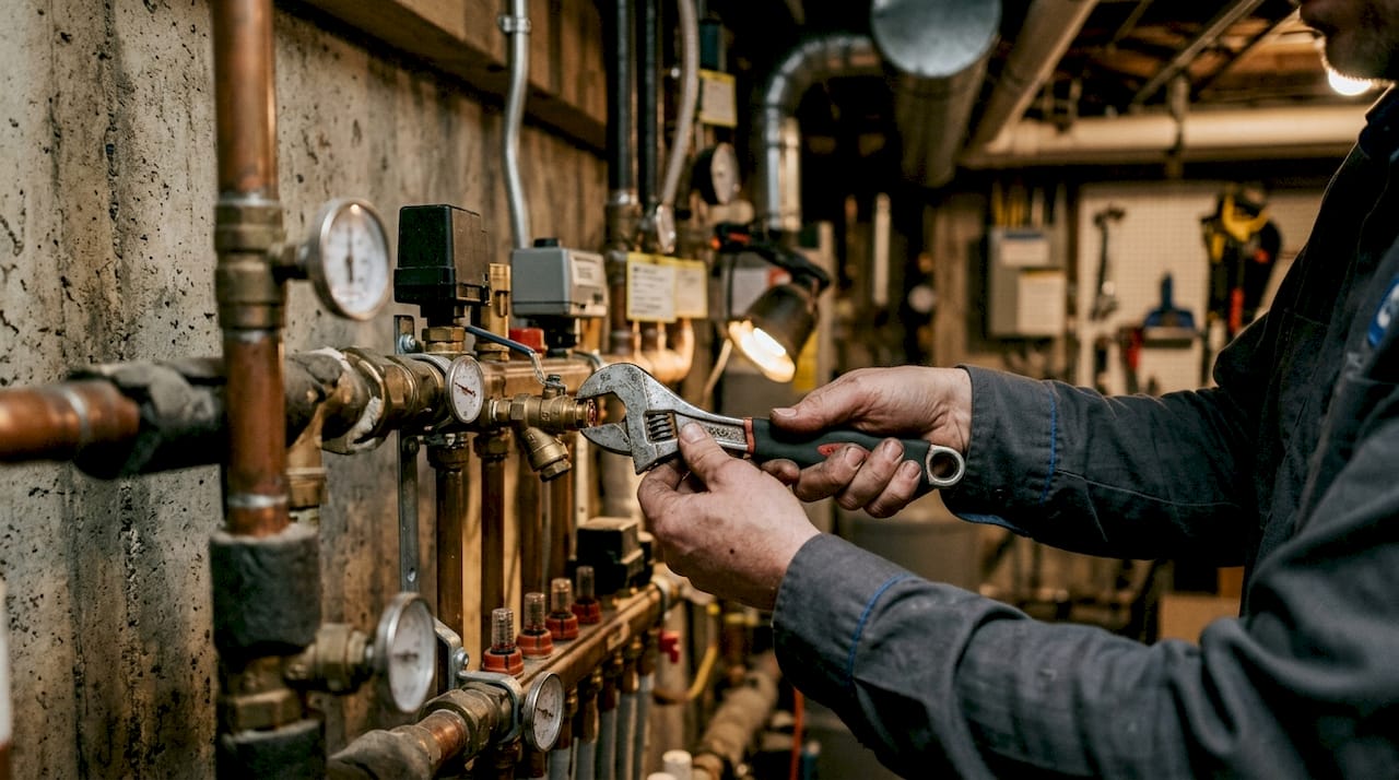
Four-pipe systems run independent hot water and chilled water loops to each terminal unit. Large commercial buildings commonly use four-pipe configurations precisely because they allow simultaneous heating in one zone and cooling in another, a requirement in facilities like hospitals, hotels, and universities where solar gain, occupancy, and internal loads vary dramatically by zone and time of day.
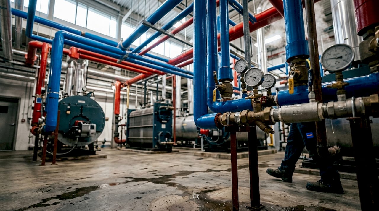
Primary-secondary systems decouple the boiler loop from the distribution loop using a common pipe section. The primary loop maintains constant flow through the boilers, protecting them from low-flow conditions that cause short cycling. Secondary pumps then serve each distribution circuit independently, allowing variable flow where it is needed without disturbing boiler operation.
Variable primary flow (VPF) systems go further by varying flow directly through the boilers using variable speed pumps. VPF systems offer superior energy efficiency compared to constant flow arrangements, though they require more sophisticated controls and careful commissioning to realise those gains.
Piping topology matters just as much as system type:
- Direct return: the first terminal unit supplied is also the first to return water to the boiler. Flow naturally favours the nearest units, so balancing valves are essential.
- Reverse return (Tichelmann layout): the supply path to the last terminal unit equals the return path, creating roughly equal circuit lengths and more inherently balanced flow.
- Series loop: terminal units are connected in sequence on a single pipe. Simple to install but offers no individual zone control and is rarely used in large facilities.
Typical heating circuit supply temperatures in Australian commercial buildings run in the range of 60°C–80°C for conventional boiler systems, with lower-temperature designs (45°C–55°C) used when heat pumps or radiant floors are the terminal units. Design delta-T (the temperature difference between supply and return) is commonly 10°C–20°C for heating circuits, with tighter deltas indicating poor flow balance or oversized pumps.
Pro Tip: Reverse return piping adds pipe length and cost upfront, but it dramatically reduces the time your team spends chasing balancing problems after commissioning. On a large campus or multi-storey building, that trade-off almost always pays off.
Why hydronic systems outperform forced-air heating in large buildings
The physics here are straightforward but worth stating plainly. Hydronic fluid acts as a conveyor belt for heat, carrying significantly more thermal energy per litre than the same volume of air. Water has roughly 3,500 times the heat capacity per unit volume of air, which means a small pipe carrying hot water can deliver the same heat output as a large duct carrying hot air. For a large building, that translates directly into smaller distribution infrastructure, less ceiling space consumed, and lower fan energy.
The practical advantages for commercial and institutional facilities include:
- Thermal comfort: radiant and convective terminal units heat people and surfaces, not just air. Occupants feel warmer at lower air temperatures, which reduces the energy needed to maintain comfort.
- Noise: hydronic systems operate quietly. There are no supply air jets, no duct rumble, and no fan noise at the terminal unit level beyond a low-speed fan coil.
- Air quality: because the system does not move air between zones, it does not redistribute dust, allergens, or pathogens through ductwork. This is particularly relevant for aged care facilities and hospitals.
- Multi-load flexibility: the same boiler plant can serve space heating, domestic hot water, snowmelt on external paths, and pool heating, all from a single central system.
- Zoning precision: each zone can be controlled independently with a zone valve and thermostat, or through a BAS with occupancy scheduling and weather compensation.
The AHRI (Air-Conditioning, Heating, and Refrigeration Institute) notes that hydronic heating delivers heat through completely sealed distribution systems with minimal losses, a characteristic that becomes more valuable as building size increases and distribution distances grow.
Pro Tip: Think of the hydronic fluid as the messenger, not the message. The boiler or heat pump generates the heat; the water simply carries it where it needs to go. Designing for efficient heat transport through the pipe network is just as important as specifying an efficient heat source.
Design, installation, and maintenance best practices for large hydronic systems
Getting a large hydronic system right starts at the design stage. Mistakes made in sizing, piping layout, or controls specification are expensive to correct once the building is occupied.
Sizing and staging heat sources
Oversized boilers and short cycling are among the most common inefficiencies in large hydronic installations. A boiler that fires briefly, satisfies the load, and shuts down repeatedly never reaches steady-state efficiency and wears out faster than one that runs at moderate load for longer periods. The solution is modular staging: multiple smaller boilers operated in sequence, with each unit sized to handle a fraction of the peak load. Schools and hospitals commonly run three or four boilers in parallel, bringing additional units online as demand rises. This approach also provides redundancy; if one boiler fails, the others carry the load.
Heat pumps are increasingly used as the primary heat source in new commercial builds, particularly where gas connections are being phased out. Air-to-water heat pumps work well in moderate Australian climates, though their output drops as ambient temperature falls, so pairing them with a gas or electric boiler as a backup or peak-load unit is common practice.
Balancing and flow measurement
Every large hydronic system needs balancing. Without it, terminal units closest to the pump receive excessive flow while distant units starve, producing uneven temperatures and occupant complaints. Commissioning engineers use manual balancing valves (set-and-forget) or automatic pressure-independent control valves (PICVs) to set design flow rates at each terminal unit. PICVs maintain their set flow rate regardless of pressure fluctuations elsewhere in the system, which makes them particularly useful in variable flow systems where pressures shift constantly.
Flow measurement at the plant level uses ultrasonic or electromagnetic flow meters installed in the main supply and return headers. These readings feed into the BAS and allow operators to verify that the system is delivering design flow rates and to detect blockages or pump faults early.
Building automation and controls
A BAS is not optional in a large hydronic system. Without automated control, operators rely on fixed setpoints that waste energy around the clock. Many commercial systems run inefficiently precisely because supply temperatures are locked at a single value regardless of outdoor conditions or actual building load. A well-configured BAS implements weather compensation, occupancy scheduling, demand-based sequencing of boilers and pumps, and fault detection alerts.
Pro Tip: Implement a functional outdoor reset on your supply water temperature. When outdoor temperatures rise, the building needs less heat, so the system should automatically lower the supply temperature rather than throttling flow. This reduces heat loss from the distribution pipework and extends boiler life by keeping return temperatures low enough for condensing operation.
Water quality and maintenance
Hydronic system water quality is a maintenance priority that is frequently overlooked until corrosion or scaling causes a failure. Untreated water promotes corrosion in steel components, scaling on heat exchanger surfaces, and biological growth in low-temperature circuits. A proper water treatment programme includes inhibitor dosing, pH monitoring, and periodic system flushing. Glycol-based antifreeze solutions are used in circuits exposed to freezing risk, such as snowmelt systems or external air handling unit coils.
Routine maintenance priorities for large systems include:
- Annual inspection of pressure relief valves and expansion tanks
- Pump seal and bearing checks every 6–12 months
- Strainer cleaning at each service interval
- Water quality testing and inhibitor top-up
- BAS sensor calibration to maintain accurate temperature and flow readings
Safety and regulatory compliance
Australian commercial hydronic systems must comply with AS/NZS 3500 (plumbing and drainage), relevant state plumbing regulations, and the National Construction Code (NCC) requirements for mechanical services. Pressure vessels including boilers and expansion tanks are subject to the Pressure Equipment (Safety) Regulation in each state. Pressure relief valves must be sized, installed, and tested to prevent over-pressurisation, and all work must be carried out by licensed plumbers and gasfitters. For electrical safety aspects of BAS wiring and pump motor connections, compliance with AS/NZS 3000 (the Wiring Rules) is mandatory.
Research-backed strategies for optimising hydronic performance
The gap between a well-designed hydronic system and a well-performing one is often wider than facility managers expect. Design intent and operational reality diverge over time as setpoints drift, sensors fail, and maintenance lapses.
Data from the US Department of Energy's work with New Ecology and the Fraunhofer Center for Sustainable Energy shows that optimising hydronic heating in multifamily and commercial buildings through data-driven analysis can reduce heating energy consumption by at least 15% and cut manual analysis time by over 80%. The same programme found that sensor-based fault detection monitoring supply and return temperatures and pump operation achieves at least 15% energy savings while preventing premature equipment wear.
Key finding: Automated fault detection and optimisation algorithms applied to large hydronic systems can achieve reductions of at least 15% in space heating energy consumption with less than a three-year payback period, based on US Department of Energy research across more than 100 multifamily buildings.
The most common operational problems identified in large hydronic systems are:
- Fixed supply temperature setpoints that ignore outdoor conditions
- Lack of real-time monitoring, meaning faults go undetected for weeks or months
- Oversized pumps running at full speed when partial load would suffice
- Poor water quality degrading heat exchanger performance over time
Variable primary flow systems address the pump energy problem directly. Switching from constant to variable primary flow offers better energy efficiency and system flexibility, though it requires more advanced control strategies and careful commissioning to realise the full benefit. For large facilities where pump energy represents a meaningful share of total mechanical plant energy, the investment in VPF controls and variable speed drives typically pays back within a few years.
For commercial HVAC installations at scale, the combination of modular heat source staging, variable speed pumping, outdoor reset, and sensor-based fault detection represents the current best practice for hydronic system performance. None of these measures requires replacing the entire system; most can be retrofitted to existing plant with targeted upgrades to controls and instrumentation.
The practical takeaway is that data acquisition comes first. Without sensors logging supply temperature, return temperature, flow rate, and pump status, there is no baseline from which to measure improvement, and no way to detect faults automatically. Installing a basic monitoring package is the single highest-leverage first step for any facility manager looking to improve an existing hydronic system.
Key takeaways
Large commercial hydronic heating systems deliver consistent, zone-specific thermal comfort at lower energy cost than forced-air alternatives, provided they are correctly sized, balanced, and monitored with automated controls.
| Point | Details |
|---|---|
| Closed-loop operation | Water circulates continuously from a central heat source through terminal units and back, maintaining an efficient heating cycle. |
| System type selection | Four-pipe systems suit buildings needing simultaneous heating and cooling; variable primary flow systems offer the best pump energy efficiency. |
| Optimisation potential | Data-driven fault detection can reduce heating energy consumption by at least 15%, with manual analysis time cut by over 80%. |
| Maintenance priorities | Water quality, sensor calibration, pressure relief valve testing, and outdoor reset configuration are the highest-impact maintenance tasks. |
| Dualflowservices | Dualflowservices provides installation, servicing, and scheduled maintenance for hydronic heating systems in commercial facilities across the Mornington Peninsula. |
Dualflowservices: local expertise for commercial hydronic systems
Running a large hydronic system well takes more than good design on paper. It takes tradespeople who understand how the system actually behaves under load, who can read a BAS fault log and trace it back to a failing sensor or a partially closed valve, and who show up when something goes wrong at 6 AM on a Tuesday.
Dualflowservices covers plumbing, electrical, and heating and cooling services across the Mornington Peninsula, including installation, scheduled maintenance, and emergency call-out for commercial hydronic heating systems. The team works with business owners, aged care facilities, retirement villages, and disability care homes, which means experience with exactly the kind of continuous-operation environments where a heating failure is not just an inconvenience. Whether you need a full system commission, a BAS integration check, or a commercial heating service assessment before winter, the team at Dualflowservices can help. Contact Dualflowservices to book a site assessment or discuss a maintenance programme for your facility.